Build note
UART: giving the chip a voice on one wire
Every part after this one is easier to debug if the chip can tell you what it thinks. Before UART, a failure looks like a dark LED. After it, the same failure prints a number.
UART is two people reading a flashing torch to each other. They have to agree on how fast the torch flashes and what a flash means, or the message arrives as noise.
The four agreements
Before the first bit means anything, both ends must agree on:
- Baud rate. How often the line may change. At 9600 baud one bit lasts about 104 microseconds.
- Bit order. Data goes out least significant bit first.
- Frame shape. One start bit, always 0. Eight data bits. One stop bit, always 1.
- Voltage sense. 0 is near 0 V, 1 is near 5 V.
There is no shared clock wire, so the receiver re-synchronises on every start bit. That is why a rate mismatch produces garbage rather than a slightly slow message.
Wiring is crossed
| ATmega328P | Pin | Connects to adapter |
|---|---|---|
TXD, PD1 |
3 | RXD |
RXD, PD0 |
2 | TXD |
| GND | 8 | GND |
One side’s mouth is the other side’s ear. The grounds must be joined, or the two ends have no common reference and every bit is a guess.
The registers
| Register | Page | Job |
|---|---|---|
UDR0 |
159 | Write a byte to send it, read a byte to receive it |
UCSR0A |
159 | Status flags, including buffer-empty |
UCSR0B |
160 | Enable the transmitter and receiver |
UCSR0C |
161 | Frame shape |
UBRR0L, UBRR0H |
162 | Baud divisor, low and high byte |
The divisor comes from one formula:
UBRR = F_CPU / (16 x baud) - 1
     = 16,000,000 / (16 x 9600) - 1
     = 103.16  ->  103
<util/setbaud.h> does that arithmetic at compile time when F_CPU and BAUD
are defined, and it also decides whether double-speed mode is needed. The code
includes it and assigns UBRR0H and UBRR0L from the macros.
Sending
void uart_init(void)
{
    UBRR0H = UBRRH_VALUE;
    UBRR0L = UBRRL_VALUE;
    UCSR0B |= (1 << TXEN0);                 // transmitter on
    UCSR0C = (1 << UCSZ01) | (1 << UCSZ00); // 8 data bits, no parity
}

void transmit_bytes(uint8_t data)
{
    loop_until_bit_is_set(UCSR0A, UDRE0); // buffer empty?
    UDR0 = data;
}
UDRE0 is the flag that says the transmit buffer can take another byte. Polling
it is fine here: 9600 baud is slow compared with the CPU, so the wait is short.
It does block, which matters later if you want to receive while sending.
DDRD must make PD1 an output first. Without that, the transmitter runs and
the pin never moves.
Printing a register as bits
The most useful function in the file is not the string printer:
void transmit_binary(uint8_t b)
{
    for (int8_t i = 7; i >= 0; i--)
        transmit_bytes((b & (1 << i)) ? '1' : '0');
}
It turns a byte into eight ASCII characters, most significant bit first. When a register does not do what the datasheet says, this shows you what is actually set instead of leaving you to decode a decimal number in your head.
What a bad baud rate looks like
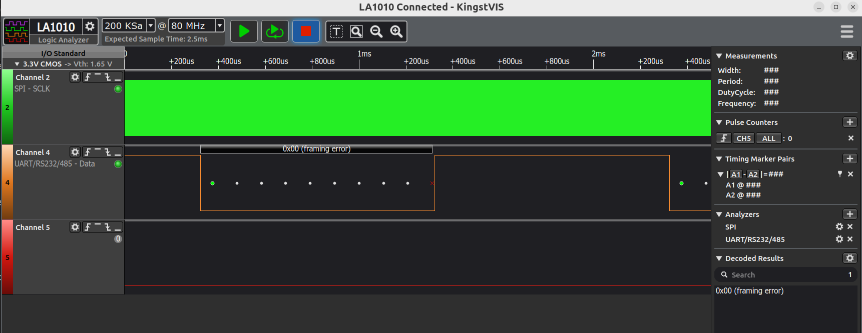
A logic analyser is the fastest way to tell a wiring problem from a settings problem. If the edges are there but the decoder reports a framing error, the receiver and transmitter disagree about the frame or the rate. If there are no edges at all, the pin is not being driven.
The failures that cost time
- Baud rate from the wrong
F_CPU. A 1 MHz chip withF_CPUset to 16 MHz gets a divisor sixteen times too small, and the output is noise. - Forgetting
DDRD. The USART happily shifts bits into a pin configured as an input. - TX and RX not crossed. Both ends talk into each other’s mouth.
- No common ground. The signal has no reference and the receiver reads nonsense.
Try this next
Enable the receiver with RXEN0 and echo every byte back. That turns the program
into a two-way terminal, and it is the foundation for the command interface the
I2C part uses to print sensor readings.
How this was made
- Written by: Rupesh, from his own
c-02-uartnotes and code, with AI drafting and editing. - Capture: Rupesh’s logic analyser.
- Numbers: from the ATmega328P datasheet and the baud formula.
- AI-assisted sections: structure and copy editing.